What to Expect from Free Models

What to Expect from Free Models

Being offered a free model to work from could potentially save time. You may even think, “Why not?” In this post, I will discuss what’s entailed when working with free models and how to determine the best approach. Use this as a guide on how to look at a model you’re given and verify that it’s what you want. I’ve outlined a process to make it easy for you to verify if the data is ready for the field.

The Surface

Most of the time when you are offered a surface file, it’s something the engineer has produced. The quality of the surface file can range from “ready-to-go” to just useless. Two explanations could be the engineering firm may have built the surface file to be used in dirt calculations (takeoff surface) or created the file for a presentation. You will not want to use either one.

The Takeoff Surface

When providing numbers for permitting and dirt use, the engineer will make a surface file. For the purpose of a takeoff, it does not need to be exact. I have long stated that if you use your takeoff surface for data, you’re spending too much time on the takeoff. Another more important reason to be wary of an engineer’s takeoff surface is that it’s generally done at the first draft of the site. Comments from agencies, owners and the utility investigation will make changes to the plans that affect the surface rendering making the takeoff surface unrelated to the final plans.

Related Article: Quantity Takeoffs in Construction: A Comprehensive Guide

The Presentation Surface

More engineers are using 3D design to produce better projects. A 3D model gives the stakeholders a better idea of what the finished job will look like. When the vertical components (e.g., buildings) are added, the improvements made to the appearance and function are easier to see and quick to update. As the design matures and gets in ground stage, 3D model updates usually stop and the focus switches to printed plan production and permitting. This is understandable and normal in the paper plan world we still live in. It will take many years for 3D models to become part of the plan submittal. In post approval, we see highway projects requiring 3D model submission for approval before paving. Civil sites are not there yet.

Surface Review

When you receive a surface file, there are several steps to confirm if it’s even worth loading in the rover. Time is money and it generally takes longer to review a surface file than to just start from scratch. To use a surface file, you’ll need to take the file apart and then reassemble it to verify it’s accurate. This will take almost double the time versus creating the file. At TOPS, we never use an engineer’s surface file for data. Our clients ask us to make it for them.   The following is the process I use to review a client surface file:

  • Inspect the file size. A surface file may be big because it represents a large area. I often see smaller surface files that are too dense and contain a lot of unneeded triangles that are hard to remove or filter.
  • Determine whether the surface is dense enough. If the triangles of the TIN are spaced too far to indicate correct details this affects accuracy. The file may get you through rough grade but a better one will be needed for finish.
  • Confirm the version. Many times the surface file is used for one of the purposes I outlined above and is an older version of the plans. We see this a lot. A quick way to tell is to look at the deltas on the plan revision box and see what type of changes happened since the file was prepared.

When the surface file has passed the above inspection, it’s time to review the quality of what you have. Be aware that any review and work you do short of a full build of the surface file can still mean problems. Be cautious.

Review Process

Always start with the most difficult parts of a surface file to model. I’ve outlined what to look for on the different project types, as well as, Field Model Requirements that can require models built for surfaces other than finish.

Civil Sites

  • Look for flat building pads and smooth sidewalks from there to the curbs.
  • Go to the parking lot and verify the storm rims are correct and look at the slopes to them. Are they smooth and in the correct direction?
  • Entrances and exits need to match up to the existing pavement. This is usually finalized in the field. Just look for big discrepancies.
  • Finally, review the retentions and landscaped areas. Check the volume of retention against the called-out requirements in the plans. Often these must change during the design process.

Field Model Requirements

  • Pad Blowups
  • Subgrade surfaces
  • Paving overbuilds for curb machines and base

Urban Streets and Subdivisions

  • Verify the COGO (Coordinate Geometry) of the centerlines.
  • Check the cross slopes of the streets.
  • Review the intersection quality. Verify the details shown match the plans. If there are no details present, look for water movement and drivability.
  • Verify the sidewalk and parkway (e.g., grass) areas that are critical to slope.
  • Confirm the 2D and 3D properties of lot and pad dimensions.

Field Model Requirements

  • Gut section (over-excavation of streets for fill by utility spoils)
  • Subgrade surface
  • Matching roadways into field shots taken at sawcut lines
  • Utility trenches

Highways

  • Verify horizontal and vertical alignments.
  • Confirm roadway width. Includes widening and intersections.
  • Review cross slope and super elevated curve transitions.

Field Model Requirements

  • Widening base for track grade
  • Subgrade surfaces
  • Non-conforming subgrades, this is where the subgrade is not parallel to the road surface or the break point of the subgrade is not at the road centerline.
  • Catch points that need to meet a field generated topo

It is possible to use a surface from an engineer as a basis measure of quality. However, when the smallest doubt arises, it is best to build it so you really know what you have.

Enhanced Data: Highways

Enhanced Data: Highways

There is nothing more difficult, or rewarding, than seeing a highway job perform well from dirt work to paving. It takes years of experience to fully understand the process. My advice is to think differently about the approach. In upcoming blog posts, I will go over the different approaches available for both Trimble Business Center and Carlson. These will be high level overviews of the enhancements we use for basic road elements. If you are a beginner, we will offer resources to get you up to speed.

Horizontal Alignment

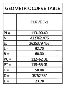
The coordinate geometry (COGO) of a road, or construction centerline, can either be a quick data entry job or an enduring nightmare. Here is an example of a curve table. When things aren’t working with the parameters entered, you will need to decide what figures to pursue and leave the rest to tweak as you go. Notice in this example the PI has two (2) different coordinates. It’s probably a typing error and a clue there is a problem ahead.       The following is a list of troubleshooting tips:

  • Enter the PC, PI, and PT coordinates and stations first. Then enter per the plan.
  • Adding the delta and the curve will help resolve calculation issues.
  • Recheck the other numbers to see how close you are to discover errors.
  • You may not need to contact the engineer if the numbers are close. However, close is relative and a lot of bad curves can affect the length of a centerline.
  • When the centerline is a median, or other non-road geometry, offsets will need to guide the actual construction. Be certain the horizontal and vertical alignments are correctly matched in all three dimensions.
  • Not all field software can handle Station Equations. The rover can decipher the information while the machine cannot. The short answer is to make two files and overlap the data a few hundred feet so the operator can make fewer file changes.

Vertical Alignment

Vertical alignments are generally not as challenging as horizontal alignments. The most common issue is reworking an asymmetrical vertical curve. I’ve listed some tips below:
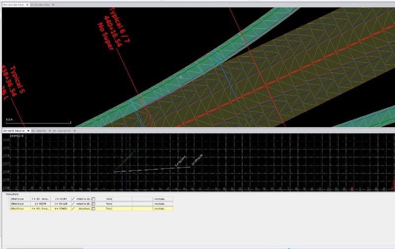
  • A road starting mid-vertical curve with no information for the PVC can either be scaled or some math should be performed to get the curve right.
  • Rehab profiles sometimes come without instructions for the new alignment. Rules need to be applied to the existing profile to identify the adjustments. The reason is when there is a mill and fill requirement, a survey crew will stake and set up the road. This should be done electronically. It takes more work since the alignment needs to be drawn or imported from a profile view in CAD. (I will describe this process in more detail in a future article.)
  • When encountering bridges, it may be tempting to ignore the vertical curves to save time. Always include them to troubleshoot design issues during construction.
  • The vertical is not always in the center of the road. Worse yet, it can shift during the job. Don’t be concerned about stopping and starting a road job at a station where this occurs.

Super Elevated Curves

Super Elevated Curves are not hard to understand. Where they are challenging is getting the standard details to match the cross sections and super diagrams. The transitions can also cause confusion. There are conflicting opinions on guidelines to use for Super Elevated Curves dependent on the state or country we are working in. The following are the general guidelines that we use.

  • Normal Crown
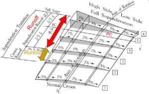
  • Runout is the length of roadway needed to accomplish a change in the outside lane cross slope from normal rate to zero.
  • Runoff is the length of roadway needed to accomplish a change in the outside lane cross slope from zero to a high side crown slope (usually 2%). Some explanations stop there and use this term to detail the rest of the transition.
  • Runup is the length of roadway needed to go from a straight cross slope percentage to full super.
  • A lot of state formulas are produced by transitioning some fraction of the curve length, usually by thirds. This diagram displays basic rules that many DOTs follow.
  • Note the axis of rotation, it can change and shift when super curves are drawn by engineers using older software. Also be aware of an old job that’s received funding and plans have not been updated.

Templates

Now that we have a good foundation for making a corridor, it’s time to attach templates to the alignments. I build roads planimetrically with as many pieces and parts required to get it right. Planimetric roads are a combination of templates and plan based features.

  • Driving lanes always require templates; at least in areas without intersections.

  • Intersections will require more data.

Using planimetric roads is advantageous when working with data that goes into the field, and is used by data collectors like templates to slope stake. Be sure to make a file that skips the staking plan details. The machines are fine with a surface. However, white paving will depend on brand.

  • Drainage elements, like ditches and culverts, are sometimes only available in plan view. They generally take a lot of time to calculate and make into a template element. Best to drop them on the screen.
  • The further you go outside the roadway, the less you need that data on the road file. Consider putting retentions and other out of bounds work into a separate grading file.

Details

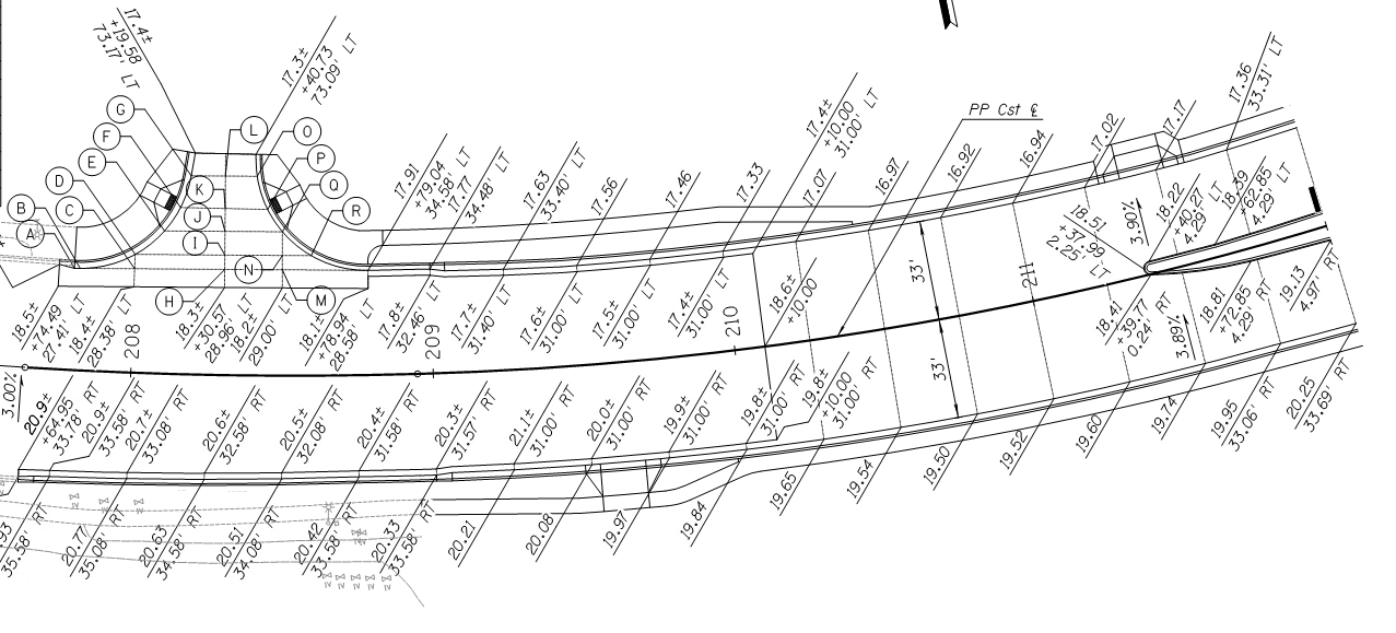
The basics are done. We have a road on the screen. It is critical to remember that we are only building part of the information on the plans. Any questions can be answered in the standard details provided by the agency. This is an example of a partial list of the standard details for a job. Questions can come up because the plans that are printed, and sent to the field, are abbreviated. There is usually no need to print the standard drawings, but if needed the drawings are easy to pull up in the job trailer. Everything from super elevation calculations to guardrail shoulders are there. You may find the plans do not reflect the standards in some areas. There may be an oversight you will need to fix in the model before going to the field.

Rideability

A lot of money is earned by meeting specs for a rideability bonus. All roading software has a way to check for the IRI, (International Roughness Index). This checks the current profile as drawn in the plans. We will often see a profile that is very close to the desired index. In other words, if the road exceeds the drawn profile by a small percentage, the index will not be met. In that case we will recommend a value engineering profile adjustment that will give the contractor a better chance of getting the bonus without affecting the road. Designers will often get a profile drawn by software, the algorithms do not take rideability into account; we are just offering the owner a chance to get a smoother ride for the user. Contractors will often get automated paving equipment paid for in a bonus depending on the size of the job. This reinforces my advice to be sure the driving lanes are produced with templates. Everything from widening to supers are better generated with templates for the software to correctly transition these and other elements.

Software

New hardware used in the field has capabilities that can benefit from the enhanced data from software. Terramodel and other previous generation tools did an adequate job but the data was not robust enough to effectively drive modern grading and paving equipment. Make sure you are giving the field the best possible information. There is usually a lot of money riding on it.  

Carlson Software and Working with Surfaces

Carlson Software and Working with Surfaces

Carlson Software is a very adaptable tool. It can run standalone by using the IntelliCAD engine or as an add-on to AutoCAD and Civil 3D. At TOPS, we all run Carlson on top of Civil 3D. In my opinion, this provides a robust, versatile work platform.

In this blog post, I want to review some of the commands that make surface production and checking easier for advanced users of Carlson Software. These commands will be useful after creating a surface that includes 2D lines, 3D lines and points.

Surface Production

A surface can be a combination of 2D lines, 3D lines and points. The following outline is a good process to organize these elements:

Layer Naming

  • Use a layer naming convention system and stay with it. At TOPS, we use different conventions for clients based on their needs and history. Avoid confusion by standardizing your conventions.
  • Be sure that anything used in a surface starts with “3D” in the layer name. This helps simplify your convention so you don’t miss something on a surface that is not included in the model.
  • To go a step further, use a layer state with just the 3D layers to make sure you are building with all the correct elements.

Above is an example of the elements used in a surface.

Initial Surface Build

It’s common to initially build a surface by fixing the obvious mistakes in order to get an idea of what needs to happen to make it perform correctly. But, it’s important to remember that the surface must meet the engineer’s intent and make a moving blade cut good base for paving and buildings. Here’s a suggested process:

First, decide on the layers necessary to make an initial surface. Understand that you may not draw breaklines or added spot elevations at this stage.

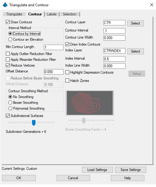
Second, open the Triangulate and Contour command and populate the settings preferred for the surface. Here are some suggestions:

  • I like to initially see the faces to watch how things tin.
  • When doing an FG surface, try to make a boundary. Shrink wrap is okay to start a finished surface job or for an OG topo. Get a tight boundary before sending to the field.
  • Prefix Layers With Surface Name adds the name for the surface to all layers used. This is an efficient way to set all the layers in one spot.
  • You can adjust the Triangle Length but I prefer to let the program make the surface then add breaklines to control length.
  • Densify Breaklines is a great feature. It will add vertices at a specified interval, like densifying a polyline without the mess during production.

  • Draw contours for a check.
  • Run Contour Intervals at .1 feet to get an idea of surface integrity.
  • Don’t label contours for this step in the process.
  • The Selection tab allows you to pick the element type for the surface. This may help if you have un-needed element types residing on a data layer. It’s best to have layers with only types you want and not rely on selection types.

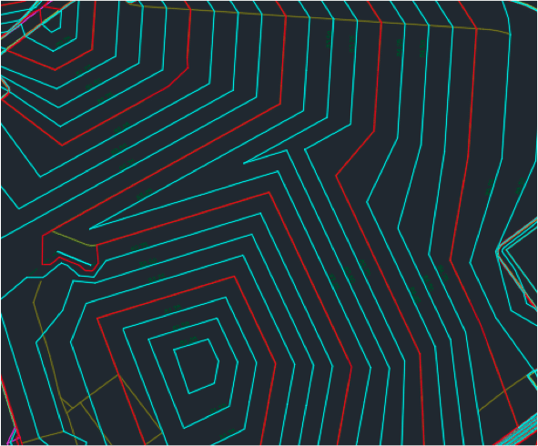
Here is the initial look at the surface:

Even with contours at a tenth of a foot, this surface does not have a lot of change in elevation. There are things we can do to make it perform better and it will be good to add breaklines in order to improve things.

When adding breaklines, the goal is to make the surface perform well when paved but more importantly it needs to work well with a grader blade that is tasked with smoothing things before paving.

This task takes practice and experimentation. There are no easy formulas to follow. Experiment and keep a good line of communication open with the field in order to get things working right.

Breaklines

After the first surface generation, I will add breaklines to the surface to make it look and work better. To apply this practice, I’ve outlined some general guidelines:

  • A breakline is nothing more than a 3D polyline. It can be generated by the software or added by the user. It’s named because it forms a grade break in a surface where it did not exist before.
  • People use too many breaklines. Don’t be afraid to try something and then delete it if you don’t like it. An example is included in the accompanying video.
  • Use the same rules for breaklines on the entire project. If you do work to make one island work, do the same changes to the others for consistency.

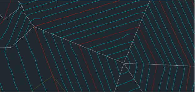
Here is a quick look at the same area shown before breaklines. The grading is now smoother and sharp grade changes have been eliminated.

In the video I will demonstrate breakline techniques that will get you on the right path to make the surface behave the way you want.

Working with Polylines

The most difficult part of data prep is working with 3D polylines. The hardest 3D lines to make are those associated with curbs in parking lots. We need to respect crossing contour lines and spots along a line representing the edge of paving or curb faces noted in the plans.

When a single line is properly made, we need to offset it to make other 3D lines in relation to the first. If we generate an edge of paving line, we will offset to make a curb bottom then top, and finally top back of curb.

Base 3D polyline creation

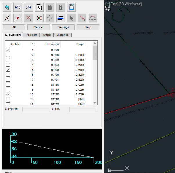
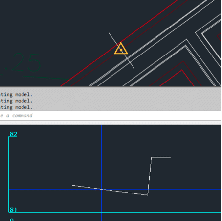
In this example, I will elevate the edge of pavement line, then move it in 3-dimensions to make the bottom face of curb and top back of curb.

The Edit Assign Polyline Elevations command now has a real-time profile view in the command to help you visualize the resulting line.

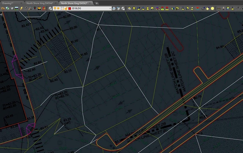
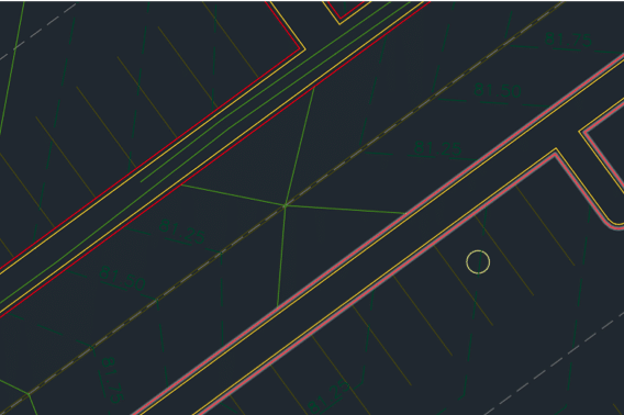
This project has contours at .25 feet. That presents its own set of problems because high and low breaks are seldom called out. This requires us to make those grade breaks. Below is a representation of one of those locations:

Contours are at 81 feet with no detail near them. Without additional work, the street would have a flat spot at the paving edges.

Always contour the site at .10 feet so that these flat spots will become obvious.

Once corrected, the surface will start to look better and perform well.

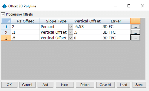
After creating a 3D line that represents what you are after, it’s now time to offset that line to get what you need. Open the Offset 3D Polyline command.

This command has great chops! There are a lot of variables in the radio buttons. I urge you to review and get used to them. For this requirement, I will use the multiple options.

The Change Layer option can be used for the other commands. There will be layer options in the next window.

With this window, we have a lot of options. I need to point some out for the best results. The Progressive Offsets checkbox takes the new line made in the next row. It makes the change to it and not just he original line being offset multiple times. We want to use that here.

We do not build curb this way. I am doing this as an example of duplicating a fill gutter and related curb elements. With the paramaters set, click OK and pick the lines you want to work with.

A quick look at the new lines in cross section show the gutter and curb details. This would not work for a grading file, this is just a good representation of what the command can do. We run the paving slope out to the face of curb then go to the top back of curb.

The command will also work for a quick pad stepdown or a blowup to get pad limits for slab prep.

The command is also useful for a simple entry road. The command will perform the change to the centerline on both sides giving you a quick roadway.

Another advantage to the command is that it will place the new lines on a layer of your choosing. At TOPS, we like to segregate 3D lines as much as possible and this command does it for us.

The Process

With the ability to create a surface and tools to adjust things, you now have the ability to get closer to what is required in the field. I say our work is 90% science and 10% art. It does not take years to get proficient at building data. However, do pay close attention to every step and the outcome of your actions to a surface. This will help you to get better faster. Focus on areas that need work initially and then step back to be sure everything works together as a good, performing surface.

Enhanced Data: Subdivisions

Enhanced Data: Subdivisions

Beyond the surface in a subdivision, there are things you can do to make your job easier. I will cover the more common tools we use to expedite planning in subdivision grading and paving jobs. I will also breakdown the improvements we’ve made beyond the simple site and linework.

Surfaces

Often there are several stages of dirt work within a subdivision. Don’t be afraid to create several surfaces for a site. Similarly, the details of the finished pad elevations, and even lot sizes, are not detailed due to the rush to get something out of the ground.

Starting with an erosion protection plan will establish several retention areas to contain site runoff during construction. These are usually basic and don’t require a lot of detail. Be sure to include any silt fencing and erosion barriers that are required in the initial work.

Streets

You can count on a lot of streets in a residential area. We have performed grading and paving data using many unique details that will help field crews. Here are a few of the models that we make:

Rough Grade Section

A great planning tool for dirt efficiency is a “gut section” model for streets. The idea is to do an over excavation of the streets so the spoils generated for utilities can stay there, and be used to get the road to subgrade in preparation for stone.

The above example shows the street to subgrade, cut straight across, ignoring the crown. We also went to 2-feet behind the curb so the curb machine can get better access. A model is built to street slopes as well so the subgrade and stone are set right.

Curbs

One of the best things to do when establishing curb grades is to give the field extended information for more efficient outcomes. We have been building curb data that helps the field for years. Here are several of the ideas that make things easier for them.

Working with Curbs

Top back of curb (TBC) grades are the base for everything that happens for streets. The sidewalk is set from that elevation to the inside. The grade is used to set string line, or made into an alignment for a guided machine. When done correctly, the street base can be graded with a laser against the top of curb and paved, even with the gutter. The issue with a curb elevation line is it is exactly that, a razor thin line that changes quickly in elevation to the inside and 1.5-2% to the outside. Often times this gives us a slightly incorrect curb elevation that seemed correct but makes for an inconsistent road.

One of the best ways to provide solid TC elevations is to do an offset line, usually about 3-feet behind the back of curb, and make a surface reflecting that.

Here is a cross section showing the finished grade sidewalk section on the right and the flat TBC offset added to the right. A couple notes:

  • The name “Curb OS” appears on the screen because I named the linestring. That’s the reason I use naming for linestrings to verify their inclusion.
  • The sidewalk on the left has a 1.5% slope. The maximum slope for a sidewalk is 2%. We bring that down the half a percent to insure the slope never goes over the max.

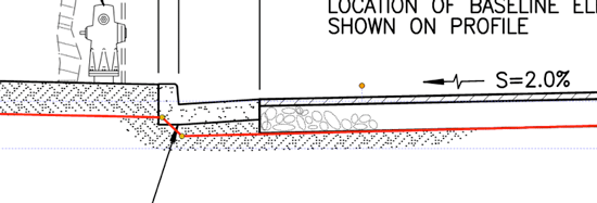
The cross section of a curb relates to how things get worked out in a slip formed curb and nothing to do with grading. We will look at what the curb does as it’s placed and what we do with the subgrade.

When we grade a road, the above (in red) is how the surface is made. The cross slope of the road is 2%, and the slope of the gutter in this typical is 6.5%. If we were to respect the gutter slope, the grader would get confused and make a mess of things, as the tip of the blade got close to the grade break.

Keeping the slope at 2% gives a bit of stone for the curb machine to plane as it makes the pouring pass. The difficulty comes in understanding what happens when you dial down to get to subgrade.

In the above diagram I am dialed down to top of native. The subgrade needs to extend out for several reasons:

  • The original ground for the curb is not excavated.
  • There needs to be an offset to provide room for the curb machine.

To make this part of the job easier, be sure the TBC line is continuous so snapping and offsetting for grading is more efficient. When placing stone, be careful to get just enough under the curb to give the curb machine something to grab to but not so much as to waste a lot of material.

When you have made a surface that has the flat TBC area, be sure to include the finished grade surface so the sidewalks and parkway sections are correct.

Lots & Pads

Lot Marking

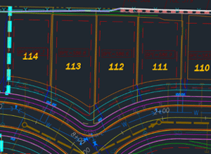
I have always wanted as much information as possible on a data collector to do my job. When it comes to marking out lots for grading sometimes you can get too much on the screen.

At the very least, you need to have the lot number and pad elevation. Here are some additions that may help in some jobs but can cause clutter if used at the same time:

  • Lot Dimensions are seldom necessary. Where we find them useful is for acre sized lots that are irregular and insure you are not grading somebody else’s property.
  • House layout lines can help to define driveways and lot grading details. They take a lot of memory due to the number of lines and detail. Clients may load and bring this on the screen late in the job.

This image is a good example of what you can put on a screen, and still keep your sanity. You would not have all the layers on at the same time. However, it is good to have grading, streets, and utilities together for convenience or for reference. Before exporting this to the data collector, I might change the lot number color from yellow to another color. It’s difficult to see in the light.

Pad Overbuilds

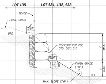
When you need to add block walls, or larger fences, to stepped pads an overbuild is usually required. This changes several things:

  • The lot line is now not the top or toe of the slope. It is necessary to maintain lot lines on your screen for clarity.
  • Some details call out overbuilds for a block wall then removing material later after it’s in. Watch the grading details closely.

This detail runs for over 50 pads in this subdivision. For this level of detail it is good to create a specific grading file for it.

The overbuild goes into the high lot 2-feet, after the wall goes in the bench and slopes are modeled to get drainage right.

Raking Pads

When a series of lots are vertically separated, usually by .3 feet or less, the grading plan calls for the pads to be sloped from the high pad to low. This is not a problem and makes the work go faster. Lot lines and pad compaction can suffer so be sure to detail these areas with good linework.

Basements

Lookout and walkout basements are an opportunity to use a lot more detail than flat pad sites. We have done everything from excavation pits and laybacks for walls to finished slopes outside the footprint to provide positive drainage between lots.

Each home site is an individual grading plan that has to be reviewed and data prepared properly. When the plan is designed well on the screen, guided excavators can make the basements quickly.

Summary

I have explained some drill down points that will help to improve accuracy in building subdivisions. The accompanying video goes over the information provided plus other details we use to improve the quality of this type of job. Included are some alternate approaches to lot and street design. Staying with design and translating that into practical models that increases efficiency is an ongoing task we take seriously.

Working with Surfaces: Trimble Business Center

Working with Surfaces: Trimble Business Center

“Software tools” is an interesting term. A tool allows you to perform work. Using the wrong tool or trying to put too many in your bag causes problems. The software tool, Trimble Business Center, utilizes commands for creating, editing and checking surfaces to help us make data that performs well in the field. We can do this quicker and more accurately than ever before but I find users get bogged down with what commands to use and when to use them. To complicate things further, as new and enhanced commands come out, users can be confused and frustrated trying to drink from the firehose of improvements.

Today I want to go over some of the commands in Trimble Business Center and talk about the best places to use them. This offering is not a training on surfaces. You can find videos on that through Trimble’s website. What this blog post will so is focus on some powerful commands that are time savers and life savers for certain situations.

I’ll reinforce some of these ideas with a video to help illustrate these concepts.

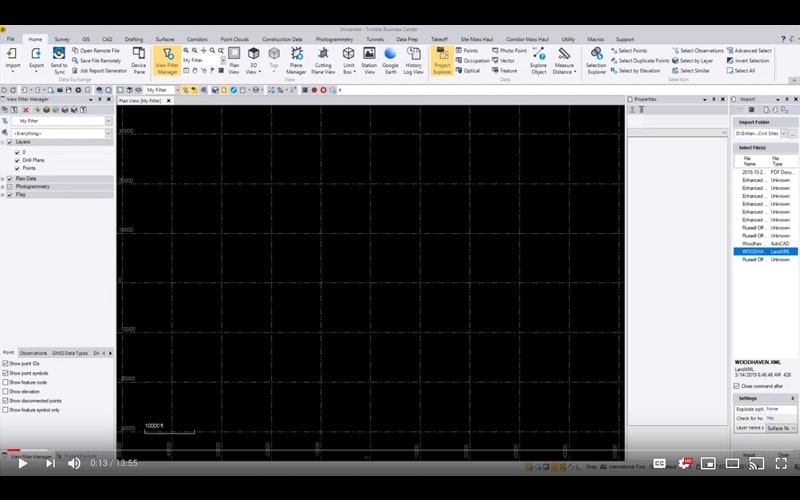
Importing a Landxml surface

Trimble Business Center has some great import options for xml surfaces. Here are some ideas:

  • Never use drag and drop for an xml surface. I like to track the import options for each type of file.
  • You may need to import the surface several different ways to get results you like.
  • Check the file header to verify units are correct.
  • If you are not certain of the quality of the surface, check detail areas for accuracy.

In the import command option, there are several options.

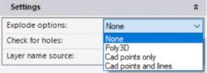
I usually don’t expand the explode options. You have several options should you decide to do so:

Try CAD Points and Lines if you want to break out surface elements. If both are present, you can have them separated to make customizing the surface easier. There is a lot more to xml. I will do an article on that particular subject in the future.

Definition of a surface

We work with a TIN (Triangulated Irregular Network) also called a DTM (Digital Terrain Model). A surface like this consists of flat triangles, often times thousands of them. The TIN produced is the representation of points, 2D, and 3D lines produced in the software during data prep. By using various commands and changing the screen elements that make up a surface, we can make it work better for our purposes.

There are options to adjust the triangles in a surface but I feel it is better to make your screen work reflect the desired outcome.

Tool Review

I want to go over some surface related commands in Trimble Business Center that are either misunderstood or have more depth than meets the eye.

Surface Properties

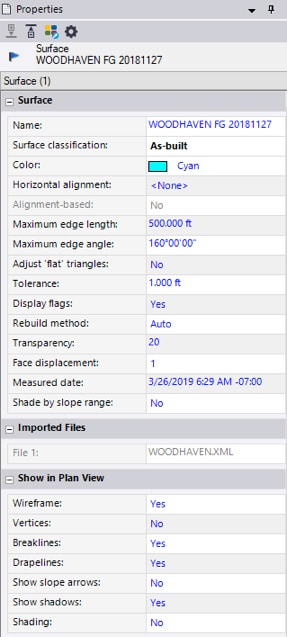
Trimble Business Center has a lot of features that seem to lurk in plain sight. The control available in the Properties of a surface is one of them.

Color – Try and set consistent colors for different surface types. It helps when you open an old job.

Horizontal alignment – A quick plan-based road (not a true corridor) greatly benefits from an alignment-based surface. Use it whenever possible.

Edge settings – I will sometimes reduce these to close off errant triangles outside my desired surface before making an edge breakline. These default settings are usually fine.

Adjust flat triangles and tolerance to help reduce flat triangles on the surface generated from imported contours.

Set rebuild method to “By User” when working with large surfaces so it will not recompute with each change.

The visualization settings will help to identify specifics during the data prep process. Experiment with toggling an item off in plan and 3D view.


Breaklines

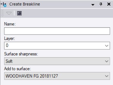
Any breakline is no more than a linestring that is part of a surface. The breakline command does several things.

  • You can name the breaklines. They can be on a selected layer and also turn up named in section views.
  • They can be placed on a separate layer.
  • Sharpness lets you control how the line is used. Soft for grading areas and sharp for curbs and walls. Sharp and texture boundary is for material sections.


Drape Objects

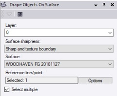
This is one of those commands in Trimble Business Center that can have additional benefit after the initial command is executed.

  • The normal attributes for what will become a 3D linestring.
  • Converts a 2D line to 3D by referencing an elevation as it crosses a TIN edge.


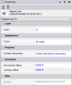
Another advantage of the resulting draped line is that it can be offset in 2D and 3D.

  • Select the draped line, right click and view the Properties.
  • You can change attributes in the Properties view.
  • Offsets can be added to the line as well.

There are times this will come in handy. The video that accompanies this article will give examples.


Merge Surfaces

The idea of merging surfaces is a simple concept but is sometimes difficult for software to process. Here is an outline:

  • There is a larger “outside surface.”
  • I want to make or insert a surface inside the boundary of that larger surface.
  • The software will trim the outside surface and transition vertically between the two.
  • This is a simplified outline. Play with the command to see how powerful it is.

The issue can be at the intersection of the two surfaces. TBC has improved this process and it performs quite well.

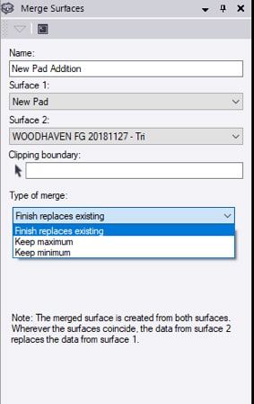
  • Name is the new Surface to make.
  • Surface 1 is the outside.
  • Surface 2 is inside, the new work.
  • A clipping boundary can be added to reduce area and file size.
  • Type of merge lets you select elevation difference or the entire surface.

Sometimes there will be spikes at difficult transitions. Review the resulting surface and make minor corrections as necessary.


Create Surface Tie

This can be used in conjunction with or instead of the merge surface command. The command is more of a design tool and can bring a lot of smaller command pieces to one place. The most common use of the command is to place a new building or house pad to a surface and view the resulting slopes and catch points.

The reference linestring can also be open and the command works well for slopes on the outside of a surface you built as it daylights into the existing ground. I will use this for a quick haul road or simple street in a subdivision.

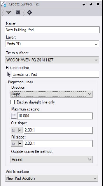
  • Name the resulting slope and daylight lines.
  • This is the layer they will reside on.
  • This is the surface your new work will tie to.
  • Just drag and click to pick projection line direction.
  • This checkbox will not show slope lines, just daylight.
  • Node distance along new linestrings.
  • Slopes can be ratios, percent, or a sharable slope table.
  • This will make the daylight line rounded or square.
  • You can add this to an existing surface. It will update the surface permanently so be careful. You can also not add to any surface, or best, make a new surface that is a combination of the tie surface and your new work.


There are more tools and ideas I will share in upcoming articles about Trimble Business Center. Get comfortable with these commands and their use in your data processing. These commands are a great way to simplify and speed up the data prep process.

Learn more about how we can help you with our 3D machine control modeling, quantity takeoff, and data preparation services

3D Data: More than Machine Control

3D Data: More than Machine Control

For many years, our business has been centered on the production of 3D data for machine control. This is the low hanging fruit of a civil site. High dollar paving, building pads, and retentions are easier to do and higher quality with machine control. Fast forward to current times.

Many civil sites are being completed with machine control. The use of the equipment on the job site has become a reality, to the point that contractors have started to look beyond their current use of the possibilities in their hands. As many of you know, I have long been a proponent of leveraging data for a job site. I have worked with many of our clients to better use the data they have in their hands and drastically improve production and profits.

I will talk about several ideas that are good next steps for users of 3D site data. These are in no particular order of profitability, any site may or may not be able to use any of these processes. Not to worry, I will back up the explanations here with a video to better explain these ideas.

2D and 3D Points

Once the domain of survey, a point has specific and relative information. I’ll use points for laying out a curb arc as an example; 3D points for the PC and PT of a curb arc give us the location and elevations of that curb run. We know the slope between the points and paving elevation is an easy calculation. Next we add the arc center as a 2D point, now there is a pivot to actually swing an arc for form or string line layout. Increasing the power of points, we offset the curb line to allow the field to set string line for a curb machine.

Site Layout

Using earthmoving equipment to get the dirt right is a huge time saver. We also advocate the use of positioning technology for more than grading;

Electrical; It started with light pole bases and quickly escalated from there. We now regularly provide data as 2D or 3D points for;

  • SES pads. The job has been checked so we are good with drainage and elevations on the site. The electrical service slab is easy to calculate from available regulations.
  • Common area in-ground power. Many plaza shopping centers have electrical connections for decorations and kiosks. Knowing the 3D location of these allows for electricians to easily set these right the first time.
  • Common area hardscape. Everything from playground equipment to benches, these additions need some type of base and connection. Know where things go and they can be done while access is easy and save re-digging to set later.

Utilities

We have been providing utility layout for years. We show points 10 feet apart on the flow-line for pipe with horizontal offsets if needed. Structures are marked as well. The advent of successful machine control for excavators has allowed us to provide a trench network so the operator can dig trenches correctly the first time.

Other utility details can benefit from information provided in the data;

  • FES’s, wing walls and valley gutters. These concrete structures are better done in rough grade but many contractors wait until near the end of construction and field fit. With a correctly prepared model there is enough confidence to build these when it’s convenient to the crew.
  • Water lines are usually specified as a minimum depth below finish grade. We build the line in the data so crews can place it at any time and not require wheel trenching making a mess of the just completed grading.
  • Subdivisions have utility connections for each lot, we handle this one of two ways;
    • We can layout all the laterals and they are placed according to plan. When it’s time to make the connection, the rover is used to find the location of the pipe.
    • When the utilities are not well defined or connections have to move, as-built shots are taken and we update the model for easy use in the future.


As-Builts

Taking shots along the way provide an ongoing record of what is being done. This helps to establish production rates as well as the basis for submittal drawings in the future. Here is one way to bring this into your workflow;

  • I call this the “daily topo walk around”. While reviewing the work being done on a site, the superintendent has a rover and takes ground topo shots as well as items being put in the ground. In a perfect world, points would be coded but that is not critical.
  • We often are asked to convert these walk around topo’s into as-builts or progress takeoffs. With the model on the screen overlaid to the topo points, we usually can figure out what the shots represent.
  • Utilities are the biggest winner with as-built points. Before covering, if the top of pipe is measured, those are later converted to as-built drawings we put together for closing submittals. Many contractors have an issue with this, and we get it. It’s one thing to get the points but now the office needs to do full blown CAD drafting and plotting.

I will help to tie these ideas together in a video linked HERE. Please don’t hesitate to ask any questions you may have regarding these or other issues.

Chasing Perfection on Civil Sites

Chasing Perfection on Civil Sites

We need to strike a balance between a picture perfect model on the screen and a well-priced practical job that performs well. Nobody wants us or their model builder to make some infinitely detailed model that would be so dense it would slow down machines. Not to worry, I’ll include a video to show you what I’m talking about.

Now to the details.

Parking lots

With the thousands of jobs we work on in any given year, parking lots are by far the most difficult. The reason is that the parameters are very specific but most plans lack sufficient information to accomplish this.

Plans should include:

  • All areas needing to drain correctly.
  • Slopes in common areas which need to support safe walking.
  • Handicapped parking spots requirements for slopes.
  • Grade breaks that will divert water to designed drainage structures.

In the past, the surveyor would blue-top spots from the plans and a grader operator would fulfill the above requirements. Now that we can do it digitally, it is important to check and verify plan intent so the blade operator can go full automatic in the field and get a good surface. When the data is not built correctly, an operator must field fix to make sure the rules are followed.

We are not going to go as far as running rainfall calculations to check engineering. We must however respect flow direction and grade breaks to deliver a smooth surface.

Here’s how:

  • Initially build the surface according to the plans. Fix obvious busts of three tenths or more.
  • Review the performance of the surface. I like to view slope arrows and create contours at a tenth of a foot which makes slope changes obvious and easier to fix.
  • Add breaklines to define the surface.

There is often a lot of time spent with small areas of a parking lot that are not working well. Experience will be the judge as to how much work it takes in order to meet the objective. Sometimes there just needs to be an extreme break over angle or varying slopes where you want a single one.

It is critical to remember how the surface is going to get from the screen to the dirt. A long grader blade is going to be making the undulations you have programmed into the file. Yes, the operator can rotate to make a narrower effective width, but it is important to consider this fact when building data.

Details

There are things we do that to me seem like a great way to increase speed and accuracy, improving margins. Here is a list of some the good and the bad:

  • Handicapped ramps. We can build a great handicapped ramp but I think common sense prevails. Machine curb will be run and the ramp cut out while the mud is still wet. We will give you linework so you know where to put the ramps but leave the curb full height.
  • Curb layout points. PC’s, PT’s, and radius points are a great way to layout hand built sections of islands and driveways. We will usually group the points by type so you can keep screen clutter down.
  • Saw cut line for turn lanes. When we get offsite plans, the existing road elevations may not be correct. Contractors will take good shots of the transition and send them off to us. We will build the entrance and propose changes in elevation where things aren’t right. We will forward that information to the engineers for approval.
  • Surface overbuilds. This is taking the outside edge of a surface three feet or more so equipment does not go out of design and need to reset wasting time. Newer control boxes are not a victim of this. If you are running older equipment then that’s OK. Don’t clutter up the screen with an overbuild if you don’t need it.

The take home message here is that data should look simple. The problem is that it takes a lot of work to make a simple looking surface. Machines and rovers have ten times the power and features than those from ten years ago. Use this to your advantage and leverage feature rich information. Your checkbook will thank you.

X